
Creating efficient CAD models for FEM simulations is not about crafting the most intricate and visually appealing designs. FEM is a computationally intensive method that necessitates meaningful and functional geometries. In this context, the principle “less is more” applies, emphasizing the importance of focusing on essential details and optimizing geometries for accurate and efficient simulations.
In TRAFOLO, there are two ways of importing geometries:
- Importing full geometries using the CAD Editor tab. It allows partitions and multiple files to be imported simultaneously. The user can then group or fuse geometries before assigning them to Geometry types.
- Importing individual geometries directly through Geometry group settings. In such a way, only one file can be imported at once, but this option provides more tools and settings for geometry manipulation after the import.
Importing through the CAD Editor tab
Consider a choke from Bel Transformer as a demonstration. It has two windings to suppress common mode noise in electronic devices. The model 3D geometry: SPDL975WM-500-2P-T.
- Click Import to select the Geometry File for import.
- Select one or multiple IGES or STEP files.
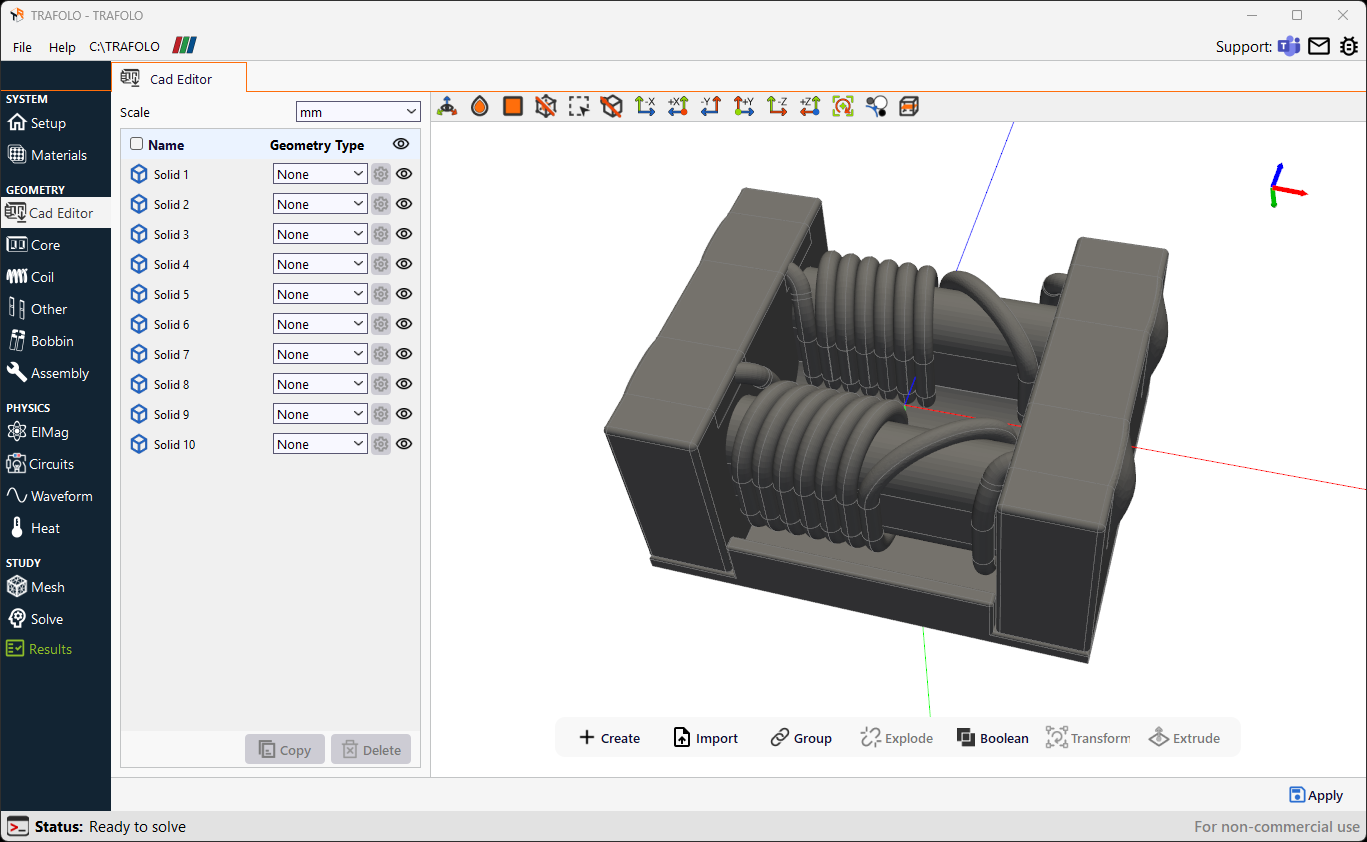
Fusing Geometries
In this example, the imported geometry consists of overlapping windings and solder. TRAFOLO requires each winding or turn to be represented as a single geometric object. This is related to the automated terminal identification and setup in later stages.

You can enable transparency on the preview toolbar to identify overlapping geometries better.
- Select all parts of the same component (e.g., a coil). To select multiple geometries, use multiselection by holding Shift and clicking on geometries.
- Fuse them using the Fuse button.

Grouping Geometries
Geometry groups reduce the number of objects the user should interact with and allow settings to be applied to multiple objects simultaneously.
- Select geometries to be grouped. To select multiple geometries, use multiselection by holding Shift and clicking on geometries.
- Click on the Group button.

Assigning Geometry Types
- Set the Geometry Type for the Core (including gaps), Coil, Other, and Bobbin geometries.
- Geometries that are unimportant for the simulation’s accuracy are kept as None. Those will not be transferred to the Geometry module.
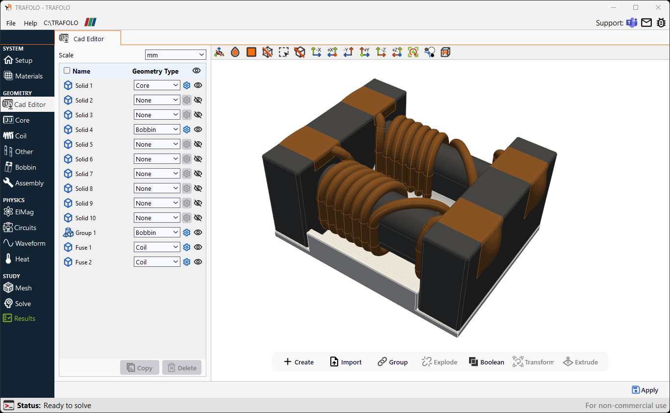
Transferring Imported Geometries to the Geometry Module
- Once all geometry types are set, click Apply (located in the bottom-right corner) to copy geometries to the corresponding Geometry tab.
- Geometry with the assigned Core type will be transferred to the Core tab as a geometry group.
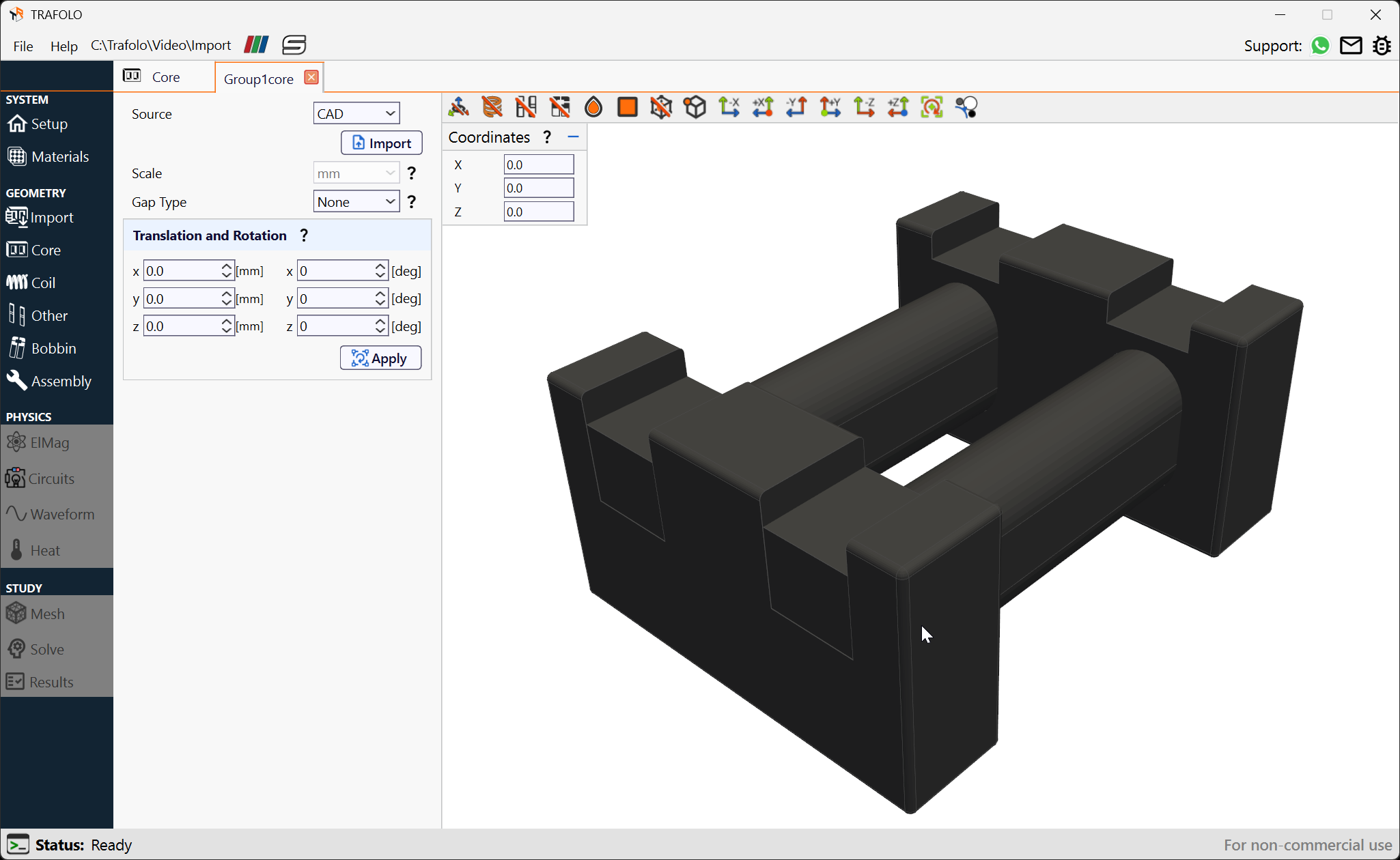
- Two windings will appear as geometry groups in the Coil Groups list.

Importing through the Geometry module
Alternatively, geometries can be imported through the corresponding Geometry tab. For example, to import a coil geometry, follow these steps:
- Create a New Group in the Coil tab. A new coil group will be added to the list.
- Open the coil group Settings.
- Change Source to CAD, and click Import.

- Provide the file path, Scale, and other settings in the Import CAD window.

- Click Ok to accept the imported geometry.
When importing CAD such way, a single file is expected. This file can contain any number of geometries such as multiple turns of core pieces with gaps.
Common issues and solutions
To create a straightforward and problem-free geometry for your simulation, consider the following key aspects for an optimal, simulation-friendly CAD file:
- Create a single solid geometry for every separate conductor: In many CAD software programs, building the coil geometry from combined blocks is common to form a complete model. When creating geometry for simulation, these blocks should be fused to form a single solid. This helps remove unnecessary faces between blocks and simplifies geometric property setup and meshing. Coil turns that are not geometrically connected do not need to be fused but can be grouped into one partition to allow easier manipulation with the entire group.
- Simplify geometry: Computer simulations represent real physical problems through a numerical model that never ultimately represents the real world. In most cases, you can disregard specific geometrical details that have minimal impact on the result.
Delete unnecessary elements and eliminate small details
In many cases, elements such as holding parts, dielectric tapes, and connections can be removed from the model. Small details have a negligible impact on simulation results. Still, they consume a lot of computation time, which needs to be resolved through meshing, significantly increasing the mesh element count.
Remove details such as small holes (fill in with the material) and gaps (use virtual gap model for core). Parts irrelevant to electromagnetics or heat removal from the core and windings can also be removed since heat transfer can be approximated using convective heat transfer boundary conditions.

Resolve inaccurately connected geometrical parts
Be cautious when connecting different parts during geometry creation. Faulty connections can result in meshing problems and calculation errors. Ensure that there are no overlaps or gaps between parts.

Ensure continuity in the magnetic component geometry
If your magnetic component features a specific channel or path, ensure it is continuous throughout the entire length to avoid meshing problems.

By following these tips for creating optimal CAD models, you will achieve a geometry that is easy to manipulate, mesh, and compute efficiently.