
In this tab, coil groups are added to the model. Later in the ElMag tab, these groups are connected and assigned to windings (e.g., primary, secondary, etc.). A winding can be made up of one or more coil groups, and each coil group can include multiple geometries, with each geometric body representing one or multiple turns.
To put it simply, the structure is: Winding > Coil Group > Turns
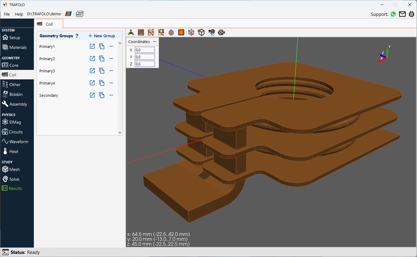
Winding geometry groups
Geometry groups – Refer to complete or partial core geometries that can be individually built from templates or imported as CAD. You can duplicate, delete, or rename these groups as needed. Individual groups can have different material properties assigned during the Assembly step.
Coil editor
In TRAFOLO, there are two approaches to creating coil groups. The first option is to use pre-defined templates, which provide a convenient starting point and produce clean geometries ideal for FEM. Alternatively, you can import coil group geometries as a single CAD file.
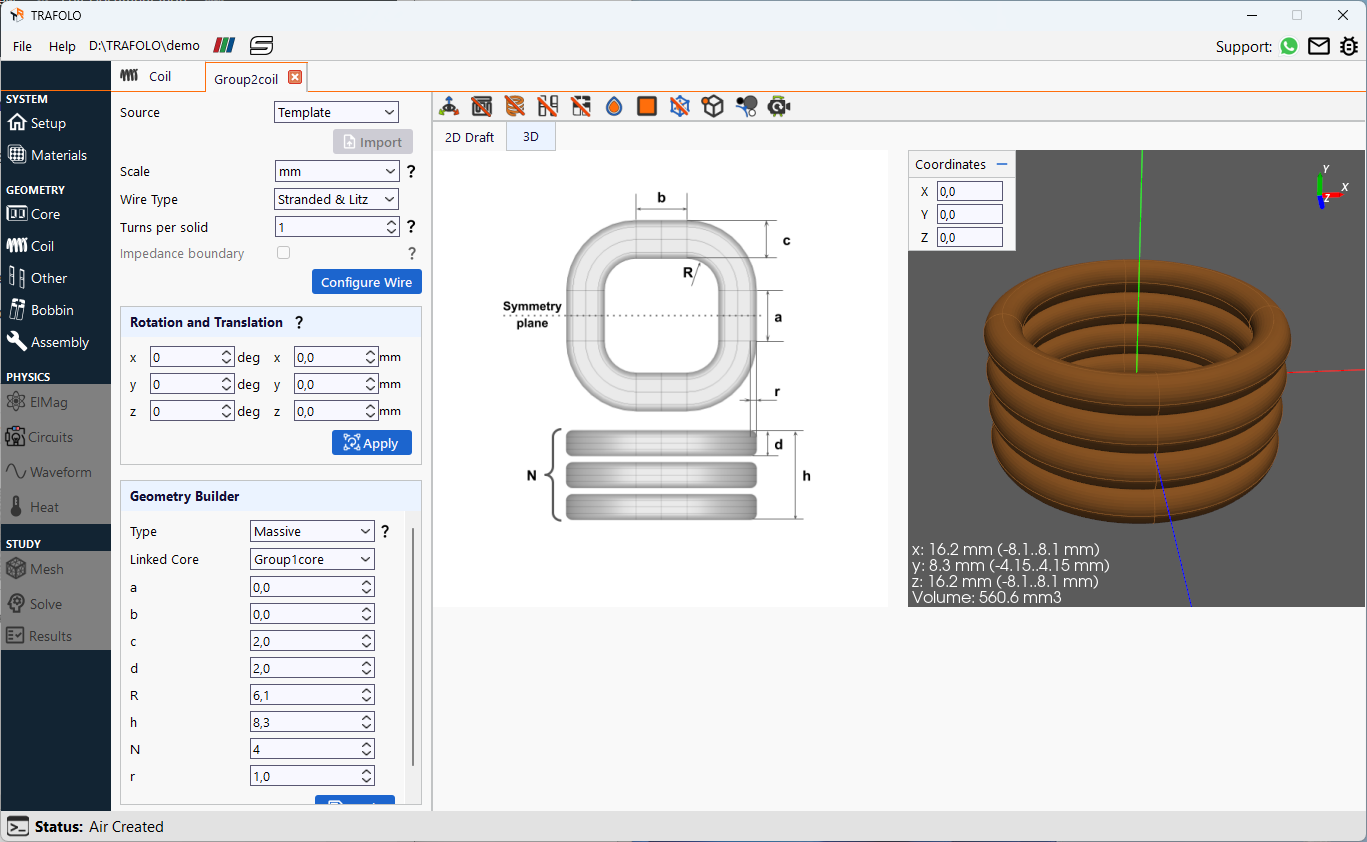
Generating winding geometries using parametric templates
IMPORTANT: Coil geometries and wire type are two different settings. Coil geometry refers to the physical layout and path of one or a bundle of wires within a winding. On the other hand, wire type in TRAFOLO refers to the numerical model used to represent the current distribution within the winding. Different wire types, such as stranded, foil, and massive, provide models for modeling currents having homogeneous, constrained in 2 dimensions, or fully resolved distributions within a wire.
Scale – The length dimensions must be set for imported geometries before importing the CAD model or creating the geometry. Once the geometry is created or imported, changing this value will have no effect, and you will need to re-import or re-build the geometry for the size setting to take effect.
Wire type:
- Stranded & Litz – used for litz/stranded wires where a stack of multiple conductors is approximated with simple geometry. The current is assumed to be uniform along the entire cross-section of the coil.
- Foil is used for thin insulated foils, sheets, or laminations combined into a single compact geometry shape. Skin effect is resolved only in one direction (parallel to the coil axis).
- Massive (solid) winding comprises separate solid wires, each representing a turn by discrete geometry. For this wire type, skin and proximity effects are fully resolved.
Turns per solid – Indicates the number of turns within each distinct geometry. For example, if a coil has five turns, each represented by a separate geometry, the value would be set to 1. In contrast, for a stranded coil where all 50 turns are approximated as a single block, the value would be set to 50. For litz wire, each individual wire is considered one turn, while strand properties are further defined under Configure Wire.
Impedance Boundary – The numerical model used specifically for solid (massive) wires when the skin depth is significantly smaller than the wire’s smallest cross-sectional dimension. It approximates the current distribution within the skin depth, removing the need for a fine boundary mesh.
IMPORTANT: This method currently cannot calculate winding losses.
Translation and Rotation – First, linear translation is applied. Then, the geometry is rotated around each axis by the specified number of degrees, starting with the x-axis, then the y-axis, and finally, the z-axis.
Configure Wire
The AC resistance and losses of the coil depend on:
- Conductor conductivity
- Wire/strand size
- Wire/strand arrangement
- Frequency
- Magnetic field strength
Various methods can be employed to account for the effects of skin effect and proximity losses in simulations.
Rac/Rdc coefficient – Assumes a constant Rac/Rdc ratio for all frequencies for a given coil. TRAFOLO uses this coefficient to adjust conductor conductivity and calculate AC resistance and losses.
Dowell’s Equation – Enables the calculation of Rac/Rdc for each coil group. The model is based on the Dowell equation and its extension for square/round and litz wires. It is assumed that losses in windings at different frequencies are independent, which is mostly the case.
- For harmonic simulation, the software calculates total winding losses by summing all losses from individual harmonics together.
- For transient simulation, first, the software applies DFT to break down the waveform into a specified number of harmonics, and then, the Rac/Rdc for each is calculated. Then, the effective Rac/Rdc is calculated using harmonics amplitudes as weights. After the simulation is completed, the calculated coefficients can be found in the Results tab. Further, read more about this model in our article.
Homogenization – A numerical model that accounts for skin and proximity effect in Litz and stranded wires without resolving individual strands, particularly in regions with non-uniform magnetic flux such as fringe flux near core gaps. Six pre-calculated parameters are added to each winding that define the interaction between strands and magnetic flux – their corrected reluctance and impedance. Currently this model works only with harmonic simulation types. Further, read more about this model in our article.
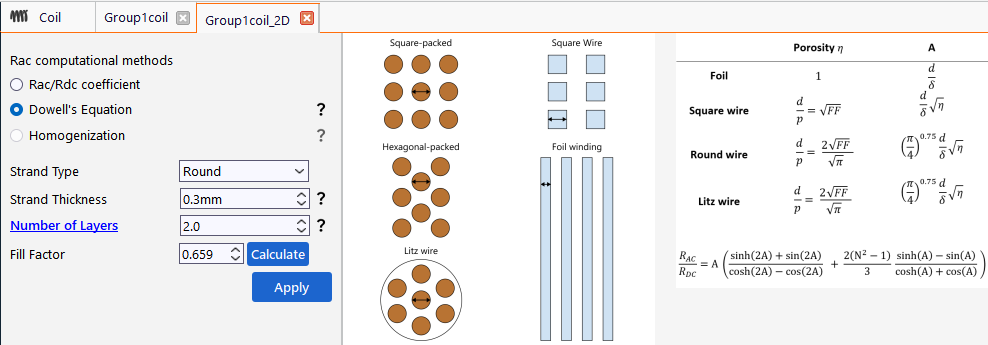
RAC/RDC proximity effect calculation for Litz, Stranded, or foil wire setups
Proximity Factor – The RAC/RDC value provided by the user. The option is only available for the RAC/RDC coefficient method.
Strand Thickness – Strand/wire/foil thickness – the diameter of a round wire, the thickness of a square wire or foil.
Number of Layers – For various wire types computed as follows:
- For round/square/foil wire, the number of winding layers refers to the number of layers;
- For Litz wire, it is determined by multiplying the number of wire layers by the square root of the total number of strands in the wire.
Nlitz_layers = Nlayers * sqrt(Nstrands)
Fill factor – Represents a fraction of conductive material in the winding geometry. This parameter affects resistance and losses in coils. Reference values:
- massive wire with discrete turns = 1
- massive wire with discrete turns and dielectric isolation <1
- square wire or foil stacked in layers <1
- round wire with orthocyclic stacking <0.91
- round wire with layer stacking <0.79
- round wire with random stacking <0.75
Geometry Builder
Type
- The filled geometry builds simple, vertical coils with rectangular cross-sections. Often used for foil as well as stranded and litz windings when resolving each wire turn is impractical.
- The massive, massive toroid, pancake, and matrix geometry types create coils with multiple separate geometries as one Coil Group. The cross-section of wires can range from round to rectangular. This option is often used for solid wires (e.g. planar) and litz wires with a few turns.
Linked Core – This feature automatically retrieves core parameters, such as the Distance Between Coils for three-phase components. If this parameter is not set, the Geometry Builder will prompt the user to provide the necessary parameters. For three-phase components this allows creating all three windings at once.
Importing from CAD
Before importing your own coil geometries, refer to our LinkedIn article about fixing CAD geometries.
A single file is expected when importing a coil group. This file can contain any number of winding turns within a single partition. For each turn, TRAFOLO searches for terminals, which requires each coil turn to consist of a single, continuous geometry. If a coil turn comprises multiple separate pieces, fusing them before importing the geometry into the software is essential. This ensures the accurate identification of terminals and the proper functioning of the simulation process within TRAFOLO.
IMPORTANT:
- Ensure that the imported partition contains non-overlapping solids.
- After assembly, every individual coil or turn geometry should have at least two terminals – faces extending to the computation domain’s exterior.
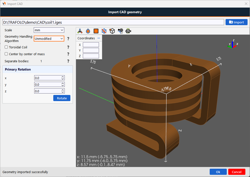
Importing winding geometry into TRAFOLO from external CAD software
Supported formats: *.step, *.stp, *.iges, and *.igs.
Geometry Handling Algorithm – Determines how the geometry, loaded from a CAD file, will be implemented into the Assembly:
- Unmodified – loads the geometry as it is and checks for any overlapping with other parts.
- Break Into Multiple Turns (Multi-object) – The imported coil consists of multiple geometries, each representing a single turn with its pair of terminals. When the symmetry plane is applied to cut the geometry, the number of turns remains unchanged, and each object functions as an individual turn.

Break into multiple turns (multi-object) – This option is used for importing coils where each turn is already represented as a separate geometry, allowing each turn to act as an independent object with its own terminals.
- Break Into Multiple Turns (Single-object) – The imported coil is initially represented as a single object encompassing the entire coil structure. However, when the symmetry plane is applied to cut the geometry, the coil is divided into multiple objects, each with its own set of terminals, and each object behaves as a separate turn.
 Break into multiple turns (single-object) – This option is used for slicing a coil, initially represented as a single object, into multiple connected turns when applying a symmetry plane. Each turn remains connected but behaves as a separate object.
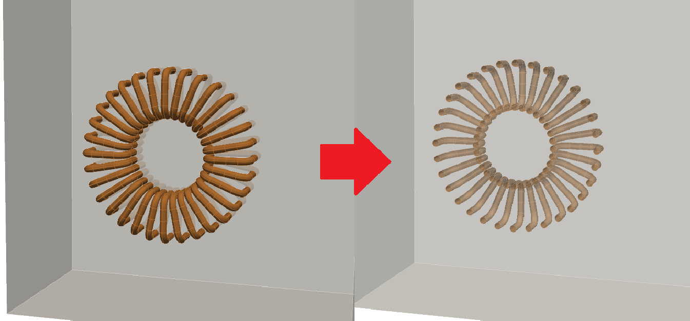
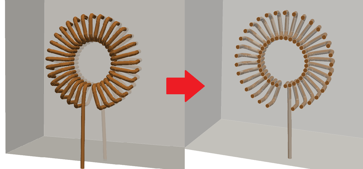
Toroidal Coil – The winding pattern is configured such that when the geometry is cut by the symmetry plane, the terminals located at the center of the core and those on the outer side are assigned to separate groups. These groups are automatically designated as the positive and negative terminals.
Center by center of mass – linearly translates geometry to its center of mass. After closing this window, you can translate geometry by coordinates.
Fuse Bodies – If a single turn consists of multiple bodies, they must be fused. This option merges imported geometries into a single body. This option can help address certain geometrical issues before Assembling.
Separate bodies – indicate the number of bodies added to the simulation after geometry is imported and processed.