
A core can consist of multiple geometries that are grouped into groups. Many settings, such as translation/rotation, magnetization, and gap definitions, are applied at the group level.

Geometry groups – Refer to complete or partial geometries that can be individually built from templates or imported as CAD. You can duplicate, delete, or rename these groups as needed.
Core editor
In TRAFOLO, there are two approaches to creating core and gap geometries. The first option is to use pre-defined templates, which provide a convenient starting point and produce clean geometries ideal for FEM. Alternatively, you can import the core geometry and gaps as a single CAD file.
The core and gaps are treated as separate bodies. The software identifies and applies corresponding materials to these parts in the Assembly tab.

Scale – The length dimensions must be set for imported geometries before importing the CAD model or creating the geometry. Once the geometry is created or imported, changing this value will have no effect, and you will need to re-import or re-build the geometry for the size setting to take effect.

After import, check the bounding box size in the preview window to ensure the geometry is correctly sized
Gap type – Gaps are regions in the core with low permeability values. Depending on the thickness of the gap, two methods can be used to model them:
- The physical gap treats gaps as solid 3D regions. For imported core geometries, gaps are defined as separate solids, while for template-built core geometries, you can define gaps by providing location and dimensions. Although gaps are initially considered part of the core, they are assigned their own material properties during the assembly step. Physical gaps should be used when the gap thickness is comparable to the core limb size and does not demand an extremely fine mesh. This approach effectively represents the magnetic field within the gap which is useful for calculating magnetic field energy, while the surrounding mesh ensures proper resolution of fringe flux.
- The virtual gap treats gaps as internal boundaries. Virtual gaps are applied to all internal faces between separate core solids. In imported and template-built geometries, you can apply a plane that can cut the core with a plane at a specified position. Reluctance conditions, based on the permeability of free space (with a relative permeability of 1) and user-provided thickness, are applied on these boundaries. This method is ideal for handling small parasitic gaps, such as the 10-30 µm gaps commonly found between two ferrite pieces assembled into a core, where meshing the gap volume would be impractical.
Translation and Rotation – First, linear translation is applied. Then, the geometry is rotated around each axis by the specified number of degrees, starting with the x-axis, then the y-axis, and finally, the z-axis.
Geometry Builder
Type
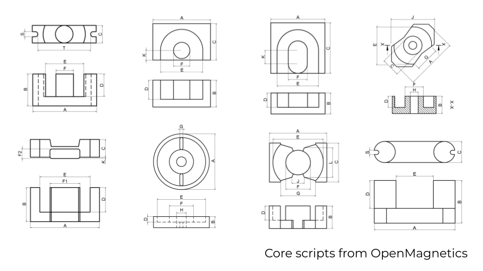
TRAFOLO provides parametric templates for the most commonly used core types:
- Two, three, four, and five limb cores are typically used for cores made of electrical steel
- Box is typically used for cores made of soft magnetic core
- Plate is typically used for wireless chargers or EMI shields
- Toroid and Cylindrical
- E / EL / EL / EFD / ER / EQ / ETD / EC / EPX
- PQ / LP
- P subtytpes
- PM subtypes
- RM subtypes
- UR subtypes
The list gets updated, so check TRAFOLO for up-to-date core types.
Gap setup table
For cores created using templates, you can specify the limb (or multiple) and coordinates of physical or virtual gaps.

For the Physical gap type, click on the New Gap button and provide the following information:
- gMin – the coordinate (Y-axis) of the gap bottom
- gMax – the coordinate (Y-axis) of the gap top
- Limb – choose which core limb to apply the gap
For the Virtual gap, set the Virtual Gap Position along the Y-axis. The virtual gap will be placed along the XZ plane.
Importing from CAD
A single file is expected when importing a core and gaps into individual geometry groups. This file can contain any number of core parts and gaps, all within a single partition. Similarly, dealing with a core that includes virtual gaps may consist of multiple core parts with common faces between them.
To ensure the imported core has the correct dimensions, compare them with the bounding box in the preview window. It is essential to select the appropriate scale before initiating the import process. If, for any reason, the core is initially loaded with incorrect length dimensions, you can reset this by selecting the proper scale and repeating the import operation.
IMPORTANT: Ensure that the imported partition contains non-overlapping solids.

Supported formats: *.step, *.stp, *.iges, and *.igs.
Geometry Handling Algorithm – Determines how the geometry, loaded from a CAD file, will be implemented into the Assembly:
- Unmodified – loads the geometry as it is and checks for any overlapping with other parts.
- Cut by Other Objects – cuts out any overlapping parts from the geometry. The priority of cutting is determined based on a hierarchy, with the winding being the highest priority, followed by the Core, Other, and the Bobbin.
Center by center of mass – linearly translates geometry to its center of mass. After closing this window, you can translate geometry by coordinates.
Fuse Bodies – Merges imported geometries into a single body. This option can help address certain geometrical issues before Assembling.
Make cut with a plane – Slice the imported geometry, enabling the application of a virtual gap. The value provided represents the Y-coordinate of the XZ plane where the cut will be made.